
DC MOTOR
A DC motor relies on the fact that like magnet poles repel and unlike magnetic poles attract each other. A coil of wire with a current running through it generates an electromagnetic field aligned with the center of the coil. By switching the current on or off in a coil its magnetic field can be switched on or off or by switching the direction of the current in the coil the direction of the generated magnetic field can be switched 180°. A simple DC motor typically has a stationary set of magnets in the stator and an armature with a series of two or more windings of wire wrapped in insulated stack slots around iron pole pieces (called stack teeth) with the ends of the wires terminating on a commutator. The armature includes the mounting bearings that keep it in the center of the motor and the power shaft of the motor and the commutator connections. The winding in the armature continues to loop all the way around the armature and uses either single or parallel conductors (wires), and can circle several times around the stack teeth. The total amount of current sent to the coil, the coil's size and what it's wrapped around dictate the strength of the electromagnetic field created. The sequence of turning a particular coil on or off dictates what direction the effective electromagnetic fields are pointed. By turning on and off coils in sequence a rotating magnetic field can be created. These rotating magnetic fields interact with the magnetic fields of the magnets (permanent or electromagnets) in the stationary part of the motor (stator) to create a force on the armature which causes it to rotate. In some DC motor designs the stator fields use electromagnets to create their magnetic fields which allow greater control over the motor. At high power levels, DC motors are almost always cooled using forced air.
The commutator allows each armature coil to be activated in turn. The current in the coil is typically supplied via two brushes that make moving contact with the commutator. Now, some brushless DC motors have electronics that switch the DC current to each coil on and off and have no brushes to wear out or create sparks.
Different number of stator and armature fields as well as how they are connected provide different inherent speed/torque regulation characteristics. The speed of a DC motor can be controlled by changing the voltage applied to the armature. The introduction of variable resistance in the armature circuit or field circuit allowed speed control. Modern DC motors are often controlled by power electronics systems which adjust the voltage by "chopping" the DC current into on and off cycles which have an effective lower voltage.
Since the series-wound DC motor develops its highest torque at low speed, it is often used in traction applications such as electric locomotives, and trams. The DC motor was the mainstay of electric traction drives on both electric and diesel-electric locomotives, street-cars/trams and diesel electric drilling rigs for many years. The introduction of DC motors and an electrical grid system to run machinery starting in the 1870s started a new second Industrial Revolution. DC motors can operate directly from rechargeable batteries, providing the motive power for the first electric vehicles and today's hybrid cars and electric cars as well as driving a host of cordless tools. Today DC motors are still found in applications as small as toys and disk drives, or in large sizes to operate steel rolling mills and paper machines.
If external power is applied to a DC motor it acts as a DC generator, a dynamo. This feature is used to slow down and recharge batteries onhybrid car and electric cars or to return electricity back to the electric grid used on a street car or electric powered train line when they slow down. This process is called regenerative braking on hybrid and electric cars. In diesel electric locomotives they also use their DC motors as generators to slow down but dissipate the energy in resistor stacks. Newer designs are adding large battery packs to recapture some of this energy.
DC motor

| Electromagnetism |
|---|
 |
|
|

The brushed DC electric motor generates torque directly from DC power supplied to the motor by using internal commutation, stationary magnets (permanent or electromagnets), and rotating electrical magnets.
Advantages of a brushed DC motor include low initial cost, high reliability, and simple control of motor speed. Disadvantages are high maintenance and low life-span for high intensity uses. Maintenance involves regularly replacing the carbon brushes and springs which carry the electric current, as well as cleaning or replacing the commutator. These components are necessary for transferring electrical power from outside the motor to the spinning wire windings of the rotor inside the motor. Brushes consist of conductors.
Brushless
Typical brushless DC motors use a rotating permanent magnet in the rotor, and stationary electrical current/coil magnets on the motor housing for the stator, but the symmetrical opposite is also possible. A motor controller converts DC to AC. This design is simpler than that of brushed motors because it eliminates the complication of transferring power from outside the motor to the spinning rotor. Advantages of brushless motors include long life span, little or no maintenance, and high efficiency. Disadvantages include high initial cost, and more complicated motor speed controllers. Some such brushless motors are sometimes referred to as "synchronous motors" although they have no external power supply to be synchronized with, as would be the case with normal AC synchronous motors.
Uncommutated
Other types of DC motors require no commutation.
- Homopolar motor – A homopolar motor has a magnetic field along the axis of rotation and an electric current that at some point is not parallel to the magnetic field. The name homopolar refers to the absence of polarity change.
Homopolar motors necessarily have a single-turn coil, which limits them to very low voltages. This has restricted the practical application of this type of motor.
- Ball bearing motor – A ball bearing motor is an unusual electric motor that consists of two ball bearing-type bearings, with the inner races mounted on a common conductive shaft, and the outer races connected to a high current, low voltage power supply. An alternative construction fits the outer races inside a metal tube, while the inner races are mounted on a shaft with a non-conductive section (e.g. two sleeves on an insulating rod). This method has the advantage that the tube will act as a flywheel. The direction of rotation is determined by the initial spin which is usually required to get it going.
Brush
_80_degree_split_ring.gif)
Permanent magnet stators
A PM motor does not have a field winding on the stator frame, instead relying on PMs to provide the magnetic field against which the rotor field interacts to produce torque. Compensating windings in series with the armature may be used on large motors to improve commutation under load. Because this field is fixed, it cannot be adjusted for speed control. PM fields (stators) are convenient in miniature motors to eliminate the power consumption of the field winding. Most larger DC motors are of the "dynamo" type, which have stator windings. Historically, PMs could not be made to retain high flux if they were disassembled; field windings were more practical to obtain the needed amount of flux. However, large PMs are costly, as well as dangerous and difficult to assemble; this favors wound fields for large machines.
To minimize overall weight and size, miniature PM motors may use high energy magnets made with neodymium or other strategic elements; most such are neodymium-iron-boron alloy. With their higher flux density, electric machines with high-energy PMs are at least competitive with all optimally designed singly fed synchronous and induction electric machines. Miniature motors resemble the structure in the illustration, except that they have at least three rotor poles (to ensure starting, regardless of rotor position) and their outer housing is a steel tube that magnetically links the exteriors of the curved field magnets.
Wound Stators
There are three types of electrical connections between the stator and rotor possible for DC electric motors: series, shunt/parallel and compound (various blends of series and shunt/parallel) and each has unique speed/torque characteristics appropriate for different loading torque profiles/signatures.
Wound stators

Series connection
A series DC motor connects the armature and field windings in series with a common D.C. power source. The motor speed varies as a non-linear function of load torque and armature current; current is common to both the stator and rotor yielding current squared (I^2) behavior[citation needed]. A series motor has very high starting torque and is commonly used for starting high inertia loads, such as trains, elevators or hoists. This speed/torque characteristic is useful in applications such asdragline excavators, where the digging tool moves rapidly when unloaded but slowly when carrying a heavy load.
With no mechanical load on the series motor, the current is low, the counter-EMF produced by the field winding is weak, and so the armature must turn faster to produce sufficient counter-EMF to balance the supply voltage. The motor can be damaged by overspeed. This is called a runaway condition.
Series motors called "universal motors" can be used on alternating current. Since the armature voltage and the field direction reverse at (substantially[clarification needed]) the same time, torque continues to be produced in the same direction. Since the speed is not related to the line frequency, universal motors can develop higher-than-synchronous speeds, making them lighter than induction motors of the same rated mechanical output. This is a valuable characteristic for hand-held power tools. Universal motors for commercial power frequency are usually small, not more than about 1 kW output. However, much larger universal motors were used for electric locomotives, fed by special low-frequency traction power networks to avoid problems with commutation under heavy and varying loads.
Shunt connection
A shunt DC motor connects the armature and field windings in parallel or shunt with a common D.C. power source. This type of motor has good speed regulation even as the load varies, but does not have the starting torque of a series DC motor. It is typically used for industrial, adjustable speed applications, such as machine tools, winding/unwinding machines and tensioners.
Compound connection
A compound DC motor connects the armature and fields windings in a shunt and a series combination to give it characteristics of both a shunt and a series DC motor. This motor is used when both a high starting torque and good speed regulation is needed. The motor can be connected in two arrangements: cumulatively or differentially. Cumulative compound motors connect the series field to aid the shunt field, which provides higher starting torque but less speed regulation. Differential compound DC motors have good speed regulation and are typically operated at constant speed.
Brushed DC electric motor
A brushed DC motor is an internally commutated electric motor designed to be run from a direct current power source. Brushed motors were the first commercially important application of electric power to driving mechanical loads, and DC distribution systems were used for more than 100 years to operate motors in commercial and industrial buildings. Brushed DC motors can be varied in speed by changing the operating voltage or the strength of the magnetic field. Depending on the connections of the field to the power supply, the speed and torque characteristics of a brushed motor can be altered to provide steady speed or speed inversely proportional to the mechanical load. Brushed motors continue to be used for electrical propulsion, cranes, paper machines and steel rolling mills. Since the brushes wear down and require replacement, brushless DC motors using power electronic devices have displaced brushed motors from many applications.
Simple Two-pole DC motor
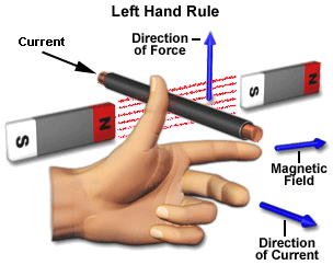
When a current passes through the coil wound around a soft iron core, the side of the positive pole is acted upon by an upwards force, while the other side is acted upon by a downward force. According to Fleming's left hand rule, the forces cause a turning effect on the coil, making it rotate. To make the motor rotate in a constant direction, "direct current" commutators make the current reverse in direction every half a cycle (in a two-pole motor) thus causing the motor to continue to rotate in the same direction.
A problem with the motor shown above is that when the plane of the coil is parallel to the magnetic field—i.e. when the rotor poles are 90 degrees from the stator poles—the torque is zero. In the pictures above, this occurs when the core of the coil is horizontal—the position it is just about to reach in the last picture on the right. The motor would not be able to start in this position. However, once it was started, it would continue to rotate through this position by momentum.
There is a second problem with this simple pole design. At the zero-torque position, both commutator brushes are touching (bridging) both commutator plates, resulting in a short-circuit. The power leads are shorted together through the commutator plates, and the coil is also short-circuited through both brushes (the coil is shorted twice, once through each brush independently). Note that this problem is independent of the non-starting problem above; even if there were a high current in the coil at this position, there would still be zero torque. The problem here is that this short uselessly consumes power without producing any motion (nor even any coil current.) In a low-current battery-powered demonstration this short-circuiting is generally not considered harmful. However, if a two-pole motor were designed to do actual work with several hundred watts of power output, this shorting could result in severe commutator overheating, brush damage, and potential welding of the brushes—if they were metallic—to the commutator. Carbon brushes, which are often used, would not weld. In any case, a short like this is very wasteful, drains batteries rapidly and, at a minimum, requires power supply components to be designed to much higher standards than would be needed just to run the motor without the shorting.
Permanent-magnet motors
Permanent-magnet types have some performance advantages over direct-current, excited, synchronous types, and have become predominant in fractional horsepower applications. They are smaller, lighter, more efficient and reliable than other singly fed electric machines.
Originally all large industrial DC motors used wound field or rotor magnets. Permanent magnets have traditionally only been useful on small motors because it was difficult to find a material capable of retaining a high-strength field. Only recently have advances in materials technology allowed the creation of high-intensity permanent magnets, such asneodymium magnets, allowing the development of compact, high-power motors without the extra real-estate of field coils and excitation means. But as these high performance permanent magnets become more applied in electric motor or generator systems, other problems are realized (see Permanent magnet synchronous generator).
Axial field motors
Traditionally, the field has been applied radially—in and away from the rotation axis of the motor. However some designs have the field flowing along the axis of the motor, with the rotor cutting the field lines as it rotates. This allows for much stronger magnetic fields, particularly if halbach arrays are employed. This, in turn, gives power to the motor at lower speeds. However, the focused flux density cannot rise about the limited residual flux density of the permanent magnet despite high coercivity and like all electric machines, the flux density of magnetic core saturation is the design constraint.
Speed control
Generally, the rotational speed of a DC motor is proportional to the EMF in its coil (= the voltage applied to it minus voltage lost on its resistance), and the torque is proportional to the current. Speed control can be achieved by variable battery tappings, variable supply voltage, resistors or electronic controls. The direction of a wound field DC motor can be changed by reversing either the field or armature connections but not both. This is commonly done with a special set of contactors (direction contactors). The effective voltage can be varied by inserting a series resistor or by an electronically controlled switching device made of thyristors, transistors, or, formerly, mercury arc rectifiers.
Series-parallel
Series-parallel control was the standard method of controlling railway traction motors before the advent of power electronics. An electric locomotive or train would typically have four motors which could be grouped in three different ways:
- All four in series (each motor receives one quarter of the line voltage)
- Two parallel groups of two in series (each motor receives half the line voltage)
- All four in parallel (each motor receives the full line voltage)
This provided three running speeds with minimal resistance losses. For starting and acceleration, additional control was provided by resistances. This system has been superseded by electronic control systems.
Field weakening
The speed of a dc motor can be increased by field weakening. This is done by inserting shunt or diverter resistances in parallel with the field winding. When the field is weakened, the back-emf reduces, so a larger current flows through the armature winding and this increases the speed. Field weakening is not used on its own but in combination with other methods, such as series-parallel control.
Simple two-pole DC motor


When a current passes through the coil wound around a soft iron core, the side of the positive pole is acted upon by an upwards force, while th


")
")


")


cdotscdotscdotscdotscdotscdots(;5;)")

")


")
")


R_a")


")

")
")


; =; frac{N_{no;load} -N_{full;load}}{N_{full;load}}X100%")
}{phi}")


 = frac{Y_B + Y_F}{2}; =; polepitch; (Y_P );=;frac{Z}{P}")
;approx ;frac{Z}{P}")