Image description

Note Book

Electrician Trade

Image description

OBJECTIVE QUESTIONS FROM CIRCUIT THEORY:


[1] A balanced RYB-sequence,Y-connected(Star Connected) source with VRN=100 volts is connected to a Δ-connected (Delta connected) balanced load of (8+j6) ohms per phase.Then the phase current and line current values respectively,are[IES2010]
(a) 10A;30A
(b) 10√3A;30A
(c) 10A;10A
(d) 10√3A;10√3A

(e) None of the above


Answer: B

[2] Assuming both the voltage sources are in phase, the value of R for which maximum power is transferred from circuit A to circuit B is [GATE2012]
(a) 0.8Ω
(b) 1.4Ω
(c) 2Ω
(d) 2.8Ω
(e) None of the above

Answer:A


[3] The voltage gain Av of the circuit shown below is [GATE2012]

(a)  |Av| ≈200
(b)  |Av|≈100
(c)  |Av|≈20
(d)  |Av|≈10
(e) None of the above

Answer:D

[4] If VA-VB=6V,  then VC-VD is [GATE2012]
(a)  -5V
(b) 2V
(c) 3V
(d) 6V
(e) None of the above

Answer:A
Solution Hint:
As Va-Vb =6  => I = V/R = 6/2 = 3A
entering current = leaving current [ KCL]
so current from Vd to Vc is same  as 3A
convert the current source to voltage source
V = IR =2 x 1 = 2V
 

Vd = Vc + 2V + (3x1)V = Vc + 5V

Vc-Vd = -5V

[5]The circuit shown is a [GATE2012]

(a) Low pass filter with f3db=[1/(R1+R2)C] rad/s
(b) High pass filter with f3db=[1/(R1C)] rad/s
(c) Low pass filter with f3db=[1/(R1C)] rad/s
(d) High pass filter with f3db=[1/(R1+R2)C] rad/s
(e) None of the above

Answer:B

[6] In the circuit shown, an ideal switch S operated at 100kHz with a duty ratio or 50%. Given thatΔic 1.6A peak-to-peak and I0 is 5A dc, the peak current in S is [GATE2012]
(a) 6.6A
(b) 5.0A
(c) 5.8A
(d) 4.2A
(e) None of the above

Answer:C 
 
Solution Hint:
Δic = 1.6A peak-to-peak
The positive peak  = Δic /2
The current flows through the switch has a peak of =  Io +  Δic /2
For your information...The current waveform is like this
 
 
The lowest point will be 5A....highest point will be 5+ 0.8

[7] The i-v characteristics of the diode in the circuit given below are 
         i={ [ V- 0.7 /500]A,   V > or = 0.7 V

                                 0A,   V< 0.7 V

The current in the circuit is [GATE 2012]
(a)  10 mA
(b)  9.3 mA
(c)  6.67 mA
(d)  6.2 mA
(e) None of the above

Answer: D
Solution Hint:
we have to find v and then apply in ct. equ...
KVL...10 = 1K * i + v
10 = 1000i +v = 1000(v-0.7/500) + v
solve it ....v= 0.8...

[8] In the following figure, C1 and C2 are ideal capacitors. C1 has been charged to 12V before the ideal switch S is closed at t=0. The current i(t) for all t is  [GATE 2012]
(a) Zero
(b) A step function
(c) An exponentially decaying function
(d) An impulse function
(e) None of the above

Answer: D
Solution Hint: 
If it is RC ckt...ie any Resistance in series with capacitor, it will be an exponentially decaying function....here no resistance...so charge instantly....ie impulse function...


[9] The impedance looking into nodes 1 and 2 in the given circuit is [GATE 2012]
(a) 50 Ω
(b) 100 Ω
(c) 5 KΩ
(d) 10.1 KΩ
(e) None of the above

Answer: A


[10] In the circuit given below,the current through the inductor is [GATE 2012]

(a)  (2/1+j)A
(b)  (-1/1+j)A
(c)  (1/1+j)A
(d)  0A
(e) None of the above

Answer: A


[1] A reactance network in the Foster's I form has poles at  ω=(infinity). The element in box-1 in the above network is  
 
(a) A capacitor
(b) An inductor
(c) A parallel LC circuit
(d) A series LC circuit
(e) None of the above
Ans: D
  
Statement for Linked Answer Questions 2 and 3: 
 
[2] For the circuit given above, the Thevinin's resistance across the terminals A and B is [GATE 2009]
(a) 0.5kΩ
(c) 1kΩ
(d) 0.11kΩ
(e) None of the above
Ans: B
 
[3] For the circuit given above, the Thevenin's voltage across the terminals A and B is 

(a) 1.25V
(b) 0.25V
(c) 1V
(d) 0.5V
(e) None of the above
Ans:D
 
[4] For the circuit shown, find out the current flowing through the 2Ω resistance. Also identify the changes to be made to double the current through the 2Ω resistance.  
 
(a) (5A; Put Vs=20V)
(b) (2A; Put Vs=8V)
(c) (5A; Put Vs=10A)
(d) (7A; Put Vs=12A)
(e) None of the above
Ans: B
 
[5] The common emitter forward current gain of the transistor shown is 100. The transistor is operating in 
 
(a) Saturation Region
(b) Cutoff Region
(c) Reverse active region
(d) Forward active region
(e) None of the above

Ans: D
 
[6] The three – terminal linear voltage regulator is connected to a 10 ohm load resistor as shown in the figure. If Vin is 10V, what is the power dissipated in the transistor 
 
(a) 0.6W
(b) 2.4W
(c) 4.2W
(d) 5.4W
(e) None of the above
Ans: B
 

LINKED ANSWER QUESTIONS: Q.7 to Q.8 

Carry Two Marks Each Statement for Linked Answer Questions:7 & 8

 
In the circuit shown, the three voltmeter readings are V1=220V, V2=122V, V3=136V
 
[7]  The power factor of the load is  
(a) 0.45
(b) 0.50
(c) 0.55
(d) 0.60
(e) None of the above
Ans: A
 
[8]  If RL=5Ω, the approximate power consumption in the load is  
(a) 700W
(b) 750W
(c) 800W
(d) 850W
(e) None of the above
Ans:B
 
Common Data Questions: 9&10
With 10V dc connected at port A in the linear nonreciprocal two-port network shown below,following were observed:
        (1)1Ω connected at port B draws a current of 3A
        (2) 2.5Ω connected at port B draws a current of 2A
 
[9] For the same network, with 6V dc connected at port A, 1Ω connected at port B draws 7/3 A. If 8V dc is connected to port A, the open circuit voltage at port B is  
(a) 6V
(b) 7V
(c) 8V
(d) 9V
(e) None of the above
Ans: C
  
[10]  With 10V dc connected at port A, the current drawn 7Ω connected at port B is  
(a) 3/7A
(b) 5/7A
(c) 1A
(d) 9/7A 
(e) None of the above
Ans:C
 

 q

[1] The period of the signal x(t) = 8 sin (0.8πt + π /4) is  
A. 0.4πs
B. 0.8πs
C. 1.25s
D. 2.5s
Ans:D
 
[2] The switch in the circuit has been closed for a long time. It is opened at t=0. At t=0+,the current through the 1μF capacitor is 
A. 0A
B. 1A
C. 1.25A
D. 5A
Ans: B
 
[3] The second harmonic component of the periodic waveform given in the figure has an amplitude of [GATE 2010]
A. 0
B. 1
C. 2/π
D. √5
Ans:A
 
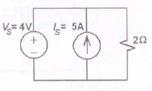
[4] As shown in the figure, a 1 resistance is connected across a source that has a load line v+i=100. The current through the resistance is  
A. 25A
B. 50A
C. 100A
D. 200A
Ans: B
 
[5] If the electrical circuit of figure (b) is an eqiuvalent of the coupled tank system of figure (a), then [GATE 2010]
A. A,B are resistances and C,D capacitances  
B. A,C are resistances and B,D capacitances
C. A,B  are capacitances and C,D resistances
D. A,C are capacitances are and B,D resistances
Ans:D
 
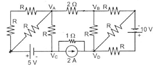
[6] If the 12Ω resistor draws a current of 1A as shown in the figure, the value of resistance R is [GATE 2010]
A. 4Ω
B. 6Ω
C. 8Ω
D. 18Ω
Ans: B
 
[7] The two-port network P shown in the figure has ports 1 and 2, denoted by terminals (a,b) and (c,d), respectively. It has an impedence matrix Z with parameters denoted by Zij. A 1Ω resistor is connected in series with the network at port 1 as shown in the figure. The impedance matrix of the modified two-port network (shown as a dashed box) is  

Ans:C
 
[8] The Maxwell's bridge shown in the figure is at balance.The parameters of the inductive coil are 
A. R=R2R3/R4, L=C4R2R3
B. L=R2R3/R4, R=C4R2R3
C. R=R4/R2R3, L=1(C4R2R3)
D. L=R4/R2R3, R=1/(C4R2R3)
Ans:A
 
Statement for Q9 & Q10:
  The L-C circuit shown in the figure has an inductance L=1mH and a capacitance C=10μF
Question [9]: The initial current through the inductor is zero, while the initial capacitor voltage is 100V. The switch is closed at t=0. The current i through the circuit is:  
A. 5cos(5x10³t)A
B. 5sin(104t)A
C. 10cos(5x10³t)A
D. 10sin(104t)A
Ans: D
 
Question [10]: The L-C circuit of statement is used to commutate a thyristor, which is initially carrying a current of 5A as shown in the figure below. The values and initial conditions of L and C are the same as in statement. The switch is closed at  t=0. If the forward drop is negligible, the time taken for the device to turn off is
A. 52μs
B. 156μs
C. 312μs
D. 26μs
Ans: A
 
[11] The voltage applied to a circuit is 100√2 cos(100πt) volts and the circuit draws a current of  10√2sin(100πt +π/4) amperes. Taking the voltage as the reference phasor, the phasor representation of the current in amperes is  
A. 10√2∠-  π/4
B. 10∠-  π/4
C. 10∠+ π/4
D. 10√2∠+ π/4
Ans:A