Image description

Note Book

Electrician Trade

Image description

Electric Motor

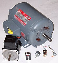
An electric motor is an electric machine that converts electrical energy into mechanical energy. The reverse conversion of mechanical energy into electrical energy is done by an electric generator.

In normal motoring mode, most electric motors operate through the interaction between an electric motor's magnetic field and winding currents to generate force within the motor. In certain applications, such as in the transportation industry with traction motors, electric motors can operate in both motoring and generating or braking modes to also produce electrical energy from mechanical energy.

Found in applications as diverse as industrial fans, blowers and pumps, machine tools, household appliances, power tools, and disk drives, electric motors can be powered by direct current (DC) sources, such as from batteries, motor vehicles or rectifiers, or by alternating current (AC) sources, such as from the power grid, inverters or generators. Small motors may be found in electric watches. General-purpose motors with highly standardized dimensions and characteristics provide convenient mechanical power for industrial use. The largest of electric motors are used for ship propulsion, pipeline compression and pumped-storage applications with ratings reaching 100 megawatts. Electric motors may be classified by electric power source type, internal construction, application, type of motion output, and so on.

Devices such as magnetic solenoids and loudspeakers that convert electricity into motion but do not generate usable mechanical power are respectively referred to as actuators and transducers. Electric motors are used to produce linear force or torque (rotary)

Electric motor


.

Motor construction


Rotor


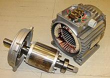
In an electric motor the moving part is the rotor which turns the shaft to deliver the mechanical power. The rotor usually has conductors laid into it which carry currents that interact with the magnetic field of the stator to generate the forces that turn the shaft. However, some rotors carry permanent magnets, and the stator holds the conductors. Devices such as magnetic solenoids and loudspeakers that convert electricity into motion but do not generate usable mechanical power are respectively referred to as actuators and transducers. Electric motors are used to produce linear force or torque (rotary).

Motor construction[edit]


Stator


The stationary part is the stator, usually has either windings or permanent magnets. The stator is the stationary part of the motor’s electromagnetic circuit. The stator core is made up of many thin metal sheets, called laminations. Laminations are used to reduce energy losses that would result if a solid core were used.

Air gap

In between the rotor and stator is the air gap. The air gap has important effects, and is generally as small as possible, as a large gap has a strong negative effect on the performance of an electric motor.

Windings


Windings are wires that are laid in coils, usually wrapped around a laminated soft iron magnetic core so as to form magnetic poles when energized with current.

Electric machines come in two basic magnet field pole configurations: salient-pole machine and nonsalient-pole machine. In the salient-pole machine the pole's magnetic field is produced by a winding wound around the pole below the pole face. In the nonsalient-pole, or distributed field, or round-rotor, machine, the winding is distributed in pole face slots.[51] A shaded-pole motor has a winding around part of the pole that delays the phase of the magnetic field for that pole.

Some motors have conductors which consist of thicker metal, such as bars or sheets of metal, usually copper, although sometimes aluminum is used. These are usually powered by electromagnetic induction.

Commutator
A toy's small DC motor with its commutator

commutator is a mechanism used to switch the input of certain AC and DC machines consisting of slip ring segments insulated from each other and from the electric motor's shaft. The motor's armature current is supplied through the stationary brushes in contact with the revolving commutator, which causes required current reversal and applies power to the machine in an optimal manner as the rotor rotates from pole to pole.[52][53] In absence of such current reversal, the motor would brake to a stop. In light of significant advances in the past few decades due to improved technologies in electronic controller, sensorless control, induction motor, and permanent magnet motor fields, electromechanically commutated motors are increasingly being displaced by externally commutated induction and permanent magnet motors.

Commutator


Electrical Motor

The motor or anelectrical motor is a device that has brought about one of the biggest advancements in the fields of engineering and technology ever since the invention of electricity. Amotor is nothing but an electro-mechanical device that converts electrical energy to mechanical energy. Its because of motors, life is what it is today in the 21st century. Without motor we had still been living in Sir Thomas Edison’s Era where the only purpose of electricity would have been to glow bulbs. There are different types of motor have been developed for different specific purposes.

In simple words we can say a device that produces rotational force is a motor. The very basic principal of functioning of anelectrical motor lies on the fact that force is experienced in the direction perpendicular to magnetic field and the current, when field and current are made to interact with each other. Ever since the invention of motors, a lot of advancements has taken place in this field of engineering and it has become a subject of extreme importance for modern engineers. This particular webpage takes into consideration, the above mentioned fact and provides a detailed description on all major electrical motors and motoring parts being used in the present era.

Classification or Types of Motor

The primary classification of motor or types of motor can be tabulated as shown below,
types of motor

History of Motor

In the year 1821 British scientist Michael Faraday explained the conversion of electrical energy into mechanical energy by placing a current carrying conductor in a magnetic fieldwhich resulted in the rotation of the conductor due to torque produced by the mutual action of electrical current and field. Based on his principal the most primitive of machines a D.C.(direct current) machine was designed by another British scientist William Sturgeon in the year 1832. But his model was overly expensive and wasn’t used for any practical purpose. Later in the year 1886 the first electrical motor was invented by scientist Frank Julian Sprague. That was capable of rotating at a constant speed under a varied range of load, and thus derived motoring action.

Among the four basic classification of motors mentioned above the DC motor as the name suggests, is the only one that is driven by direct current. It’s the most primitive version of the electric motor where rotating torque is produced due to flow of current through the conductor inside a magnetic field.

Rest all are A.C. electrical motors, and are driven by alternating current, for e.g. the synchronous motor, which always runs at synchronous speed. Here the rotor is an electro - magnet which is magnetically locked with stator rotating magnetic field and rotates with it. The speed of these machines are varied by varying the frequency (f) and number of poles (P), as Ns = 120 f/P.

In another type of AC motor where rotating magnetic fieldcuts the rotor conductors, hence circulating current induced in these short circuited rotor conductors. Due to interaction of the magnetic field and these circulating currents the rotor starts rotates and continues its rotation. This is induction motor which is also known as asynchronous motor runs at a speed lesser than synchronous speed, and the rotating torque, and speed is governed by varying the slip which gives the difference between synchronous speed Ns , and rotor speed speed Nr,

It runs governing the principal of EMF induction due to varying flux density, hence the name induction machine comes. Single phase induction motor like a 3 phase, runs by the principal of emf induction due to flux, but the only difference is, it runs on single phase supply and its starting methods are governed by two well established theories, namely the Double Revolving field theory and the Cross field theory.

Apart from the four basic types of motor mentioned above, there are several types Of special electrical motors like Linear Induction motor(LIM),Stepper motor, Servo motor etc with special features that has been developed according to the needs of the industry or for a particular particular gadget like the use of hysteresis motor in hand watches because of its compactness.
                                                           animated dc motor

Working of Electric Motor

The electric motor is a device which converts electrical energy to mechanical energy. There are mainly three types of electric motor.
1) DC Motor
2) Induction Motor
3) Synchronous Motor.
All of these motors work in more or less same principle. Working of electric motor mainly depends upon the interaction of magnetic field with current.
Now we will discuss the basic operating principle of electric motor one by one for better understanding the subject.


Working of DC Motor

Working principle of DC Motor mainly depends upon Fleming Left Hand rule. In a basic dc motor, an armature is placed in between magnetic poles. If the armature winding is supplied by an external dc source, current starts flowing through the armature conductors. As the conductors are carrying currentinside a magnetic field, they will experience a force which tends to rotate the armature. Suppose armature conductors under N poles of the field magnet, are carrying currentdownwards (crosses) and those under S poles are carryingcurrent upwards (dots). By applying Fleming’s Left hand Rule, the direction of force F, experienced by the conductor under N poles and the force experienced by the conductors under S poles can be determined. It is found that at any instant the forces experienced by the conductors are in such a direction that they tend to rotate the armature.
Again, due this rotation the conductors under N – poles come under S – pole and the conductors under S – poles come under N – pole. While the conductors go form N – poles to S – pole and S – poles to N – pole, the direction of currentthrough them, is reversed by means of commutator. Due to this reversal of current, all the conductors come under N - poles carry current in downward direction and all the conductors come under S – poles carry current in upward direction as shown in the figure. Hence, every conductor comes under N – pole experiences force in same direction and same is true for the conductors come under S – poles. This phenomenon helps to develop continuous and unidirectional torque.
                                  

Working of Induction Motor

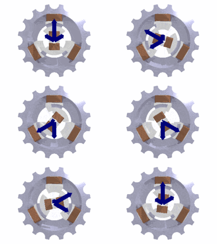
Working of electric motor in the case of induction motor is little bit different from dc motor. In single phase induction motor, when a single phase supply is given to the stator winding, a pulsating magnetic field is produced and in athree phase induction motor, when three phase supply is given to three phase stator winding, a rotating magnetic fieldis produced. The rotor of an induction motor is either wound type or squirrel cadge type. Whatever may be the type of rotor, the conductors on it are shorted at end to form closed loop. Due to rotating magnetic field, the flux passes through the air gap between rotor and stator, sweeps past the rotor surface and so cuts the rotor conductor. Hence according toFaraday’s law of electromagnetic induction, there would be a induced current circulating in the closed rotor conductors. The amount of induced current is proportional to the rate of change of flux linkage with respect to time. Again this rate of change of flux linkage is proportional to the relative speed between rotor and rotating magnetic field. As per Lenz lawthe rotor will try to reduce the every cause of producingcurrent in it. Hence the rotor rotates and tries to achieve the speed of rotating magnetic field to reduce the relative speed between rotor and rotating magnetic field.


Working of synchronous Motor

In synchronous motor, when balanced three phase supply is given to the stationary three phase stator winding, a rotatingmagnetic field is produced which rotates at synchronous speed. Now if an electromagnet is placed inside this rotatingmagnetic field, it is magnetically locked with the rotatingmagnetic field and the former rotates with the rotatingmagnetic field at same speed that is at synchronous speed.